Process engineering for factories: from mass balance to P&ID
Before there is a building drawing, there is a process to be calculated. We build the design basis, the material and energy balances, the simulation model, the equipment sizing, and the process documents, then derive the building from those.

The process first, the building after
On a factory project the order runs one way. The process fixes the equipment list. The equipment list fixes the demand for power, steam, compressed air, cooling, and effluent treatment. That utility demand and those machine foundations then fix the column grid, the clear height, and the floor loading.
Design the building first and let the process follow, and the process has to be forced into space that already exists. That reappears later as floor slabs broken out for pits, switchboards short of capacity, and variations that were never in the budget. Putting process engineering at the front is the cheapest way to avoid it.
What the process scope covers.
Eight areas of work. On a new plant they are usually taken in sequence; on an operating plant, often only two or three are relevant.
-
Process Design Basis
The document that fixes what is actually being designed, before any drawing exists. Without it every later calculation stands on an assumption nobody wrote down.
- Capacity basis, feed specification, and product specification stated as an operating range rather than a single point
- Process route selection and flowsheet choice, including why the alternatives were set aside
- Recycle architecture: which streams return, to which point, and what accumulates if nothing is purged
- Operating window: the pressure, temperature, and conversion that remain safe and remain controllable
- Battery limits, utility tie-in points, and the responsibility boundary between packages
- Design assumptions recorded one by one, so they can be retested when field data arrives
-
Material & Energy Balances
The calculation that sizes almost everything downstream. A balance that does not close is a finding, not something to be tidied until it appears to.
- Component material balances across every unit, recycle and purge streams included
- Energy balances: heating and cooling duty, heat of reaction, and the utility demand of each unit
- Conversion, yield, and process loss calculations, with the location of each loss stated plainly
- Thermal efficiency of fired equipment and exchangers, computed from data that can be traced back
- Balance closure checks, and honest reporting of the gap where field data is inconsistent
- Balances used as the basis for equipment sizing, not filed as a report appendix
-
Process Simulation
A steady-state model used to test cases, not to produce numbers that look convincing. The thermodynamic method chosen is reported alongside the result it produced.
- Steady-state modelling of the full unit train, from feed through to product
- Property package selection and the reason for it: equations of state for hydrocarbon systems, activity-coefficient models for polar and azeotropic systems
- Columns, exchangers, reactors, and rotating equipment modelled on one consistent flowsheet
- Case studies and sensitivity analysis on pressure, feed temperature, reflux ratio, and recycle rate
- Reconciliation of hand calculation against simulation, reported as a parameter-level deviation table
- The model’s validity limits written down: what conditions were modelled, what data was not regressed, and what still needs field testing
- The model file handed over in the simulator format agreed in the contract, so your own team can open it and carry it forward after the project closes
-
Separation & Distillation Systems
The part of a process that consumes the most energy and most often decides whether product specification is met. An azeotrope is not solved by adding trays.
- Tray or packing selection, theoretical and actual stage count, feed stage location, and reflux ratio
- Column diameter and height, tray spacing, and pressure drop through the column
- Column hydraulic checks: flooding, weeping, and downcomer loading across the required turndown range
- Azeotrope handling: extractive or azeotropic distillation, entrainer selection, and entrainer recovery for recycle
- Vacuum operation where the separation demands a lower bottoms temperature, including what that costs the condenser and vacuum system
- Multi-column trains: separation sequence, condenser and reboiler integration, and a complete stream table
-
Process Equipment Sizing
From process conditions to dimensions, materials, and a datasheet that can be tendered. It stays a conceptual design until vendor data arrives.
- Reactors: residence time, working volume, jacket duty, and agitator type and power
- Vessels, tanks, and separation drums, with holdup time and superficial velocity calculations
- Heat exchangers: duty, transfer area, temperature approach, and flow configuration, with class and construction to TEMA
- Thermal rating verified in the exchanger rating software agreed for the project, with the result set against the hand calculation
- Pumps and compressors: head, shaft power, operating point against the curve, and available versus required NPSH
- Material selection against corrosion and operating temperature, including the reason for stepping up to a given stainless grade
- Equipment datasheets and an equipment list as the tender basis, with design and operating conditions stated separately
-
Heat Integration & Energy Efficiency
Recovering heat the process already contains before buying new utility. An opportunity on paper is not yet a feasible installation.
- Mapping heat sources and sinks across the flowsheet, including condenser and cooler duty currently thrown away
- Designing recovery loops: condenser heat to feed preheat, outlet heat to a compressor stage, and similar links
- Removing exchangers that integration makes redundant, rather than stacking new ones on top
- Pressure adjustment and flow rebalancing to cut utility load without moving the product specification
- Temperature-approach, controllability, and start-up and shutdown checks on every integration scheme
- Schemes that fail the controllability check reported as not feasible, with the reason stated
-
Performance Evaluation & Debottlenecking
For plants already running. The work starts from field data we collect ourselves, not from old drawings that may no longer match the plant.
- Collecting field operating data and checking it for consistency before it is used to calculate anything
- Comparing actual operating conditions against manufacturer curves and against the original design condition
- Thermal efficiency, mass loss, and the location of any deviation from the design balance
- Parallel pump train evaluation: each unit’s operating point, the cause of degradation, and load balancing between units
- Pressure and temperature sensitivity analysis to recover purity or capacity without replacing major equipment
- Recommendations ranked, starting with what can be done at the lowest level of modification
-
Process Safety & Control
A process is judged by how it fails, not only by the purity it reaches. This is the part that makes a design operable by people rather than merely calculable.
- Control philosophy and loop list: what is controlled, by what, and what happens when a controller loses its signal
- Interlock and trip schedule, with the safe state each trip drives the plant to
- Pressure relief sizing basis and relief scenarios, prepared for review by the authorised party
- HAZOP preparation and close-out, with every action tracked through to closure
- Operating risk review: exothermic reactions, pressurised systems, flammable inventory, and work on live systems
- Management-of-change discipline, so a mid-project design change cannot pass without being rechecked
What heat integration does to a flowsheet.
The two diagrams below are the same process before and after heat integration. What changes is not the product but where the heat comes from: external utility duty is replaced by heat the process already contains, and one exchanger is no longer needed at all.
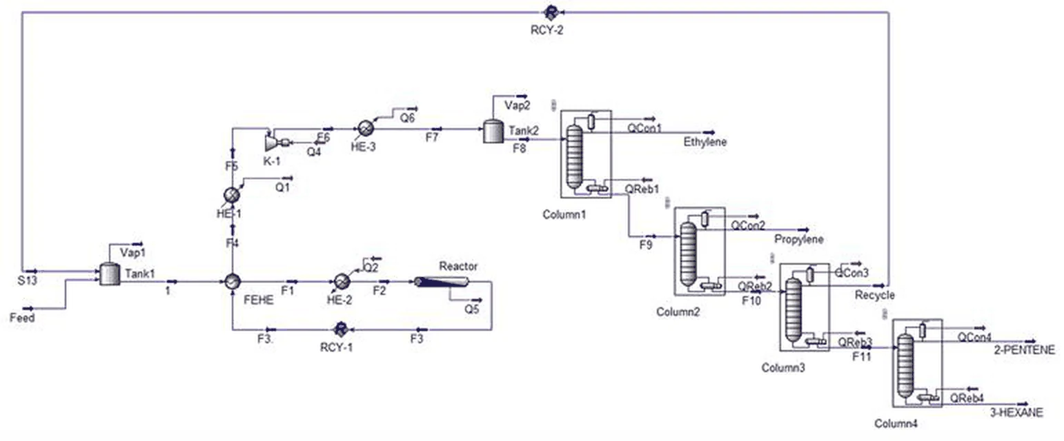
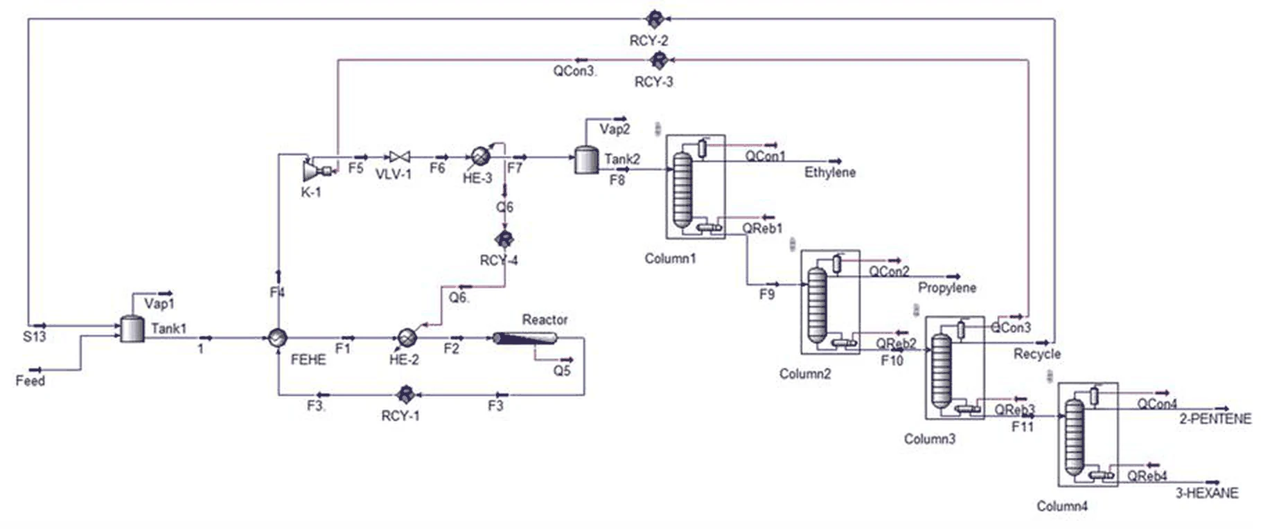
These diagrams are used as a method illustration, taken from a published process engineering study, and are not drawings of a TCC project. A scheme like this shows an opportunity, not yet a feasibility: temperature approach, controllability through start-up and upset, and retrofit cost all still have to be calculated before anything is installed.
What a result means, and what it does not.
Process calculation produces numbers that look definite. Those numbers are always tied to particular assumptions, conditions, and methods, and it is the assumptions that most often get lost when a report changes hands.
So every output we issue carries its validity limits. Where something has not been verified, it is written down as not verified rather than left to read as though it had been.
| A simulation result | A model output at the stated conditions and property package. Not a measurement, and no substitute for a field test. |
|---|---|
| A conceptual sizing | A basis for tender and layout. Before execution it still needs vendor data, relief sizing, mechanical-code review, and HAZOP. |
| A balance from field data | Only as good as the instrument data behind it. A balance that does not close is reported with its gap, not smoothed until it looks tidy. |
| An energy saving claim | Always stated against a named baseline. Retrofit feasibility, temperature approach, controllability, and cost are separate calculations. |
| Hand calculation versus simulation | Reported as a parameter-level deviation table, never as one headline agreement figure that hides where the gap sits. |
| Client process data | Treated as confidential. Never used as an example, a reference, or promotional material without written permission. |
The documents you receive.
- Process design basis document with its assumption register
- Material and energy balance report per unit
- Simulation model file, the cases run, and the property package used
- Process Flow Diagram (PFD) and stream table
- Piping and Instrumentation Diagram (P&ID)
- Equipment list, equipment datasheets, and material specifications
- Sizing calculation report with the correlations and sources it used
- Control philosophy, loop list, and interlock schedule
- Deviation table of hand calculation against simulation
- A statement of validity limits and what still requires field verification
| Inside a TCC EPC contract | Process engineering runs inside Phases 01 and 02, before layout and structure are locked. This is the cheapest order, because the building is derived from the process. |
|---|---|
| Standalone process design package | Design basis, balances, simulation, sizing, PFD, and P&ID delivered as a document package, without taking the construction work. |
| Evaluation of an operating plant | Field data collection, performance evaluation, and debottlenecking or energy-recovery proposals for a plant that keeps producing. |
| Review of a third-party design | A check over the balances, assumptions, sizing, and process documents prepared by another consultant, with findings issued in writing before we sign anything. |
Questions we are asked
- What is the difference between process engineering and factory building design?
- Building design answers how the building stands up. Process engineering answers what happens inside it: material flow, reaction, separation, and heat. The order matters. The process fixes the equipment list, the equipment list fixes the utility demand and the machine foundations, and together those fix the column grid and clear height. Design the building first and the process has to be forced into it, which is what usually reappears mid-project as a variation.
- Can the process engineering be bought without the construction work?
- Yes. The process design package is delivered as documents: design basis, balances, simulation model, sizing, PFD, P&ID, and datasheets. You are free to tender the construction to anyone. We also work the other direction, reviewing a process design prepared by another consultant and issuing the findings in writing.
- Can a simulation result be used directly for procurement?
- No, and we say so in every report. A simulation result is a model output at a stated condition and property package. For procurement it has to be completed with vendor data, relief sizing, mechanical-code review, and HAZOP. What can be used directly is an equipment datasheet that states design and operating conditions separately, because vendors bid against the design condition.
- Can you evaluate a running plant without stopping production?
- Yes, and it is the most commonly requested evaluation scope. Data is collected under normal operating conditions, then reconciled against manufacturer curves and the design condition. Recommendations are ranked, starting with load balancing and pressure adjustment that need no equipment replacement, and only then the proposals that require a shutdown window.
- How is process data kept confidential?
- Process data, recipes, and operating conditions belong to the client and are treated as confidential. We do not present client projects, figures, or data as examples on this site or in any material without written permission. A confidentiality agreement can be signed before the first data is sent.
- Which industries is this scope suited to?
- Plants whose product comes from reaction, separation, or heat transfer rather than assembly. That covers chemicals and petrochemicals, edible oil processing, food and beverage, pharmaceuticals and their active ingredients, water and wastewater treatment, and utility systems such as steam, compressed air, and process cooling.
- Which process simulator is used?
- What decides the quality of a model is not the brand of simulator but the property package chosen and the quality of the feed data. The same model can be built in any commercial simulator and still be wrong if the property package is wrong. The simulators commonly used for work of this kind are Aspen HYSYS, Aspen Plus, ChemCAD, and DWSIM. Which one is used on your project, and who provides the licence, is settled in the contract at the outset. The deciding factor is not our preference but that the model file can be opened, checked, and carried forward by your own team once the project closes.
- Can you check or continue an existing simulation model?
- Yes, and it is a frequent request. The check starts where the errors usually are: the property package chosen, the feed specification, the degrees of freedom on each unit, and recycle loops that never truly converged. Findings come back as a parameter-level deviation table against hand calculation, not as a general verdict that the model is good or bad. The file is returned in its original format, together with a record of what we changed.
- Can PFD and P&ID development be ordered on its own?
- Yes, with one condition: a drawing can only be produced from a stated basis. Where the material balance and equipment list already exist, the PFD, stream table, and P&ID can be built straight from them. Where they do not, we establish that basis first, because a P&ID drawn without a balance and without a control philosophy only moves somebody else’s assumptions into the drawing, and they travel on from there into procurement.
- Is this the same as an energy audit?
- No, and the difference is worth stating up front. An energy audit in the regulatory sense carries its own scope, reporting format, and auditor requirements. What we do is a process energy efficiency evaluation: mapping heat sources and sinks across the flowsheet, finding utility load that heat integration can remove, then testing whether the scheme stays controllable through start-up and upset. It can feed a formal energy audit, but it does not replace one.
Where it sits in the work sequence.
Inside an EPC contract, process engineering runs across the first two phases, and its outputs are used for the rest of the project: the equipment sizing becomes the procurement basis, and the design basis becomes what commissioning tests against.
Tell us about the project.
Send the outline: location, approximate area, process type, and target production start. We will come back with the questions that need answering before any number means anything.